As we step into the new year, we’re excited to embrace fresh opportunities, set new goals, and continue our journey of growth and innovation. At Nanjing D.L.T Sling, Ltd Looking back at the past year, we’ve made significant strides in improving our manufacturing processes and enhancing the quality of our https://www.dlt-sling.com/products. Our commitment to excellence has allowed us to serve our clients better, meet industry standards, and earn their trust. We’ve also expanded our product range, making sure we meet the diverse needs of our customers while maintaining the high level of safety and efficiency that we’re known for. As we enter the new year, we have set ambitious yet achievable goals. One of our main objectives is to strengthen our presence in international markets and to continue building lasting relationships with our global partners. We’re focused on increasing our daily outreach, ensuring that we introduce our premium https://www.dlt-sling.com/products to more customers around the world. Additionally, we aim to improve our internal operations by embracing new technologies and streamlining our production processes. This will allow us to continue producing high-quality https://www.dlt-sling.com/products, like our heavy-duty slings At Nanjing D.L.T Sling, Ltd. Our focus on safety will remain a top priority, with a continued commitment to maintaining our CE and GS certifications, ensuring that each product we produce meets the highest safety standards. We believe that success comes from strong partnerships. Our team is excited to continue collaborating with our clients, suppliers, and partners. We value the feedback and trust of our clients and will work harder than ever to meet their needs with customized solutions and outstanding service. As we look to the future, we know that with teamwork, innovation, and dedication, we will achieve even greater success. We’re excited about the opportunities this year holds and look forward to working together to make it our best year yet! On behalf of Nanjing D.L.T Sling, Ltd.
How are neodymium magnets used in microwaves?
The Basics of Neodymium Magnets
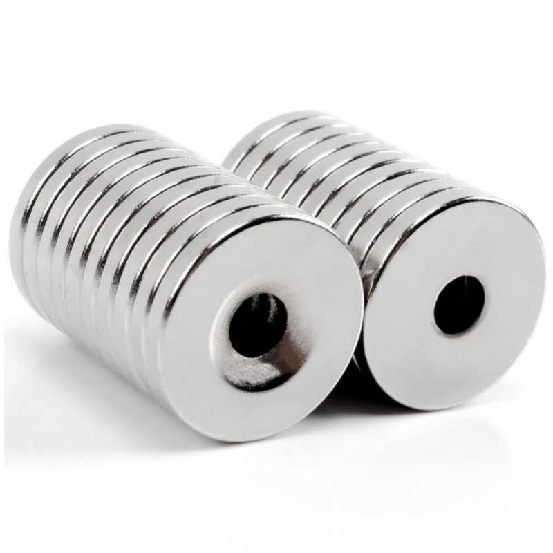
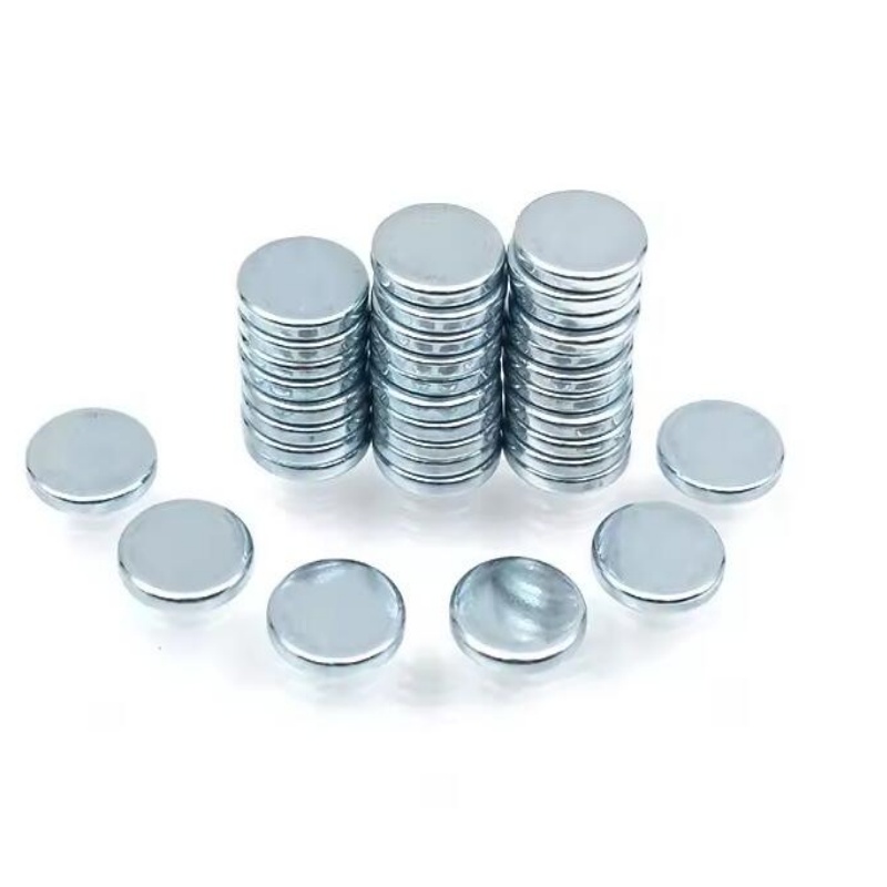
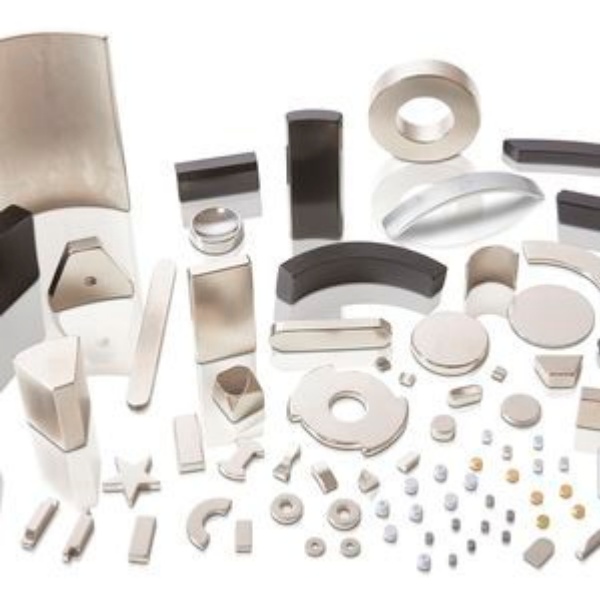
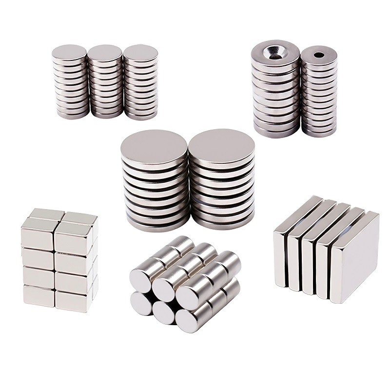
Neodymium magnets are rare-earth magnets composed of neodymium, iron, and boron, known for their exceptional strength and versatility, have a wide range of applications in modern technology. One of the lesser-known uses is in microwave ovens, where they play a critical role in improving efficiency and functionality. Good performance neodymium magnets are the strongest type of permanent magnet commercially available, offering a high magnetic field strength in a compact size. These properties make them ideal for applications where space and power are limited, such as in household appliances.
Magnets in the Magnetron
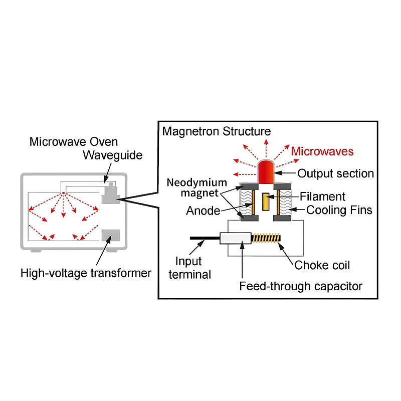
At the heart of every microwave oven is a device called a magnetron, which generates the microwave radiation used to heat food. Neodymium magnets are often used in the magnetron to direct and focus the electron stream that creates microwaves. Their strong magnetic fields ensure the electrons move in a controlled spiral pattern, producing consistent and efficient microwave energy.
Improving Efficiency and Compact Design
Using powerful rare earth magnets allows microwave manufacturers to design smaller, more energy-efficient appliances. Traditional magnets might require larger components or higher power consumption to achieve similar performance. With neodymium magnets, the compact size of the magnetron can be maintained without compromising on power, making modern microwaves more space-efficient and environmentally friendly.
Applications Beyond Heating
Some advanced microwaves incorporate additional features, such as sensors or rotors for even cooking. Small strong neodymium magnets can also be used in these components to enhance performance. For example, they might be part of a motor that drives a turntable or a sensor system that optimizes cooking times.
Conclusion
Neodymium magnets are indispensable in the design and functionality of modern microwave ovens. Their unparalleled strength and compact size enable better efficiency, enhanced performance, and innovative features. As technology continues to advance, the role of these magnets in household appliances is likely to expand further.

Which wearable devices are suitable for using neodymium magnets?
As wearable technology takes the world by storm, one tiny but mighty component is proving to be essential for its success: the strong neodymium magnet. Known for their incredible magnetic strength and compact size, neodymium magnets are rapidly becoming the unsung heroes behind some of the most innovative devices on the market, from smartwatches to wireless earphones.

The power of neodymium magnets lies in their ability to deliver high magnetic force without compromising on size. In a world where smaller, lighter, and more efficient devices are the goal, these magnets allow manufacturers to pack more punch into less space. For instance, in wireless earphones, neodymium magnets drive the speakers and microphones, delivering clear, high-quality sound without taking up valuable room. The strong magnetic field ensures smooth operation even in these ultra-compact devices, making them both functional and comfortable.
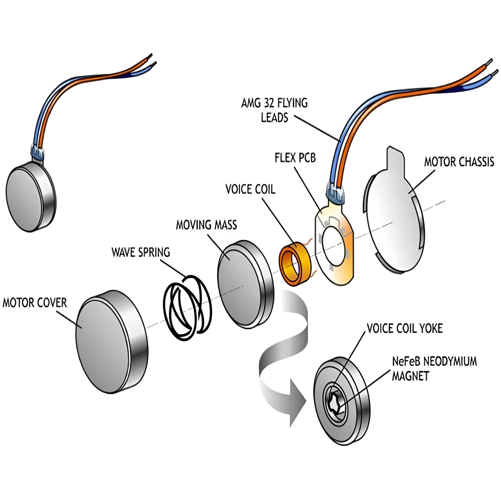
In addition to audio applications, neodymium magnets play a critical role in the motors used within wearable devices. Take the smartwatches, for example—neodymium magnets power the vibration motors that send haptic feedback or notifications to users. Their exceptional efficiency allows these motors to run on minimal energy, extending battery life and enhancing the overall user experience. With wearable devices increasingly being designed to offer longer battery life and more sophisticated features, excellent quality neodymium magnets are becoming indispensable.
The surge in wearable tech adoption, driven by advancements in health tracking, fitness monitoring, and even augmented reality, is pushing the demand for these strong, tiny magnets even higher. Manufacturers are constantly seeking ways to make devices smaller, more powerful, and more user-friendly, and neodymium magnets are often the solution. These magnets help to keep wearable devices not only functional but also sleek and lightweight, which is essential for the growing market.
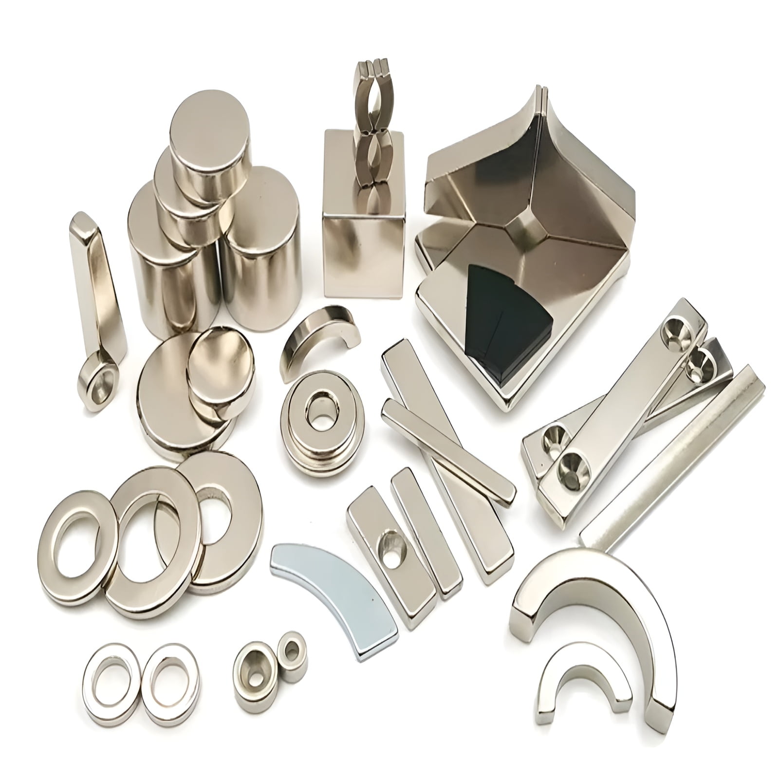
Specializing in the production of high-precision neodymium magnets, we provide customized solutions that cater to the exacting demands of wearable devices. Whether it's adjusting size, shape, or coating, we ensure our magnets enhance performance, durability, and energy efficiency—all while keeping your products as compact as possible.
Looking ahead, the role of professional customized neodymium magnets in wearable technology will only continue to grow. As wearable devices become more advanced, these magnets will remain at the core of innovation. With their superior strength and small footprint, neodymium magnets are set to drive the next wave of wearable technology, pushing the boundaries of what's possible and making everyday life smarter, more efficient, and more connected.
What are the functions of neodymium magnets in magnetic shielding?
Magnetic shielding is a critical technology used to manage and control magnetic fields, particularly in sensitive environments where electromagnetic interference (EMI) can disrupt equipment performance. While super powerful neodymium magnets are primarily known for their strength, they also play a significant role in creating effective magnetic shielding solutions. Below we explore how neodymium magnets contribute to magnetic shielding and highlight their applications and potential for future development.
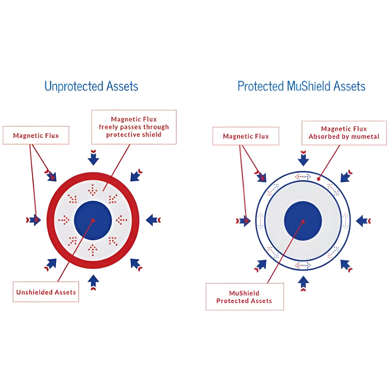
The Concept of Magnetic Shielding
Magnetic shielding is the process of redirecting or reducing magnetic fields to protect sensitive components from interference. It involves the use of materials that can absorb or redirect magnetic flux lines, minimizing their impact on nearby objects. Neodymium magnets, with their strong and stable magnetic fields, are often utilized in conjunction with shielding materials to optimize these effects.
Neodymium Magnets in Magnetic Shielding
One of the key properties of neodymium magnets that makes them suitable for magnetic shielding is their ability to influence and guide magnetic fields effectively. By strategically placing professional custom neodymium magnets, engineers can manipulate the magnetic flux in ways that reduce interference or isolate specific areas. Their compact size and high magnetic energy make them ideal for applications where space is limited, such as in precision electronics and medical devices.
Applications of Magnetic Shielding Using Neodymium Magnets
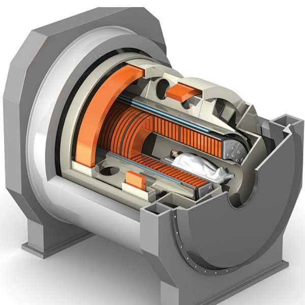
1. Medical Equipment: Magnetic shielding is essential in medical imaging devices like MRI machines. Neodymium magnets help manage stray magnetic fields, ensuring accurate imaging results and protecting nearby equipment from interference.
2. Electronic Devices: In modern electronics, shielding is crucial to prevent EMI from disrupting sensitive circuits. Neodymium magnets can be integrated into shielding designs to enhance the effectiveness of the barriers.
3. Scientific Research: In laboratories, neodymium permanent magnets are used in experimental setups requiring controlled magnetic environments. They help minimize external magnetic noise, enabling precise measurements.
Optimizing Magnetic Shielding Designs
To maximize the effectiveness of magnetic shielding with neodymium magnets, engineers often focus on:
- Magnet Arrangement: By carefully arranging magnets, magnetic flux lines can be redirected to minimize interference.
- Combination with Shielding Materials: Pairing neodymium magnets with high-permeability materials like mu-metal or permalloy enhances shielding effectiveness.
- Custom Shapes and Sizes: Customizing the shape and size of neodymium magnets ensures they fit specific applications, improving both performance and efficiency.
Conclusion
Neodymium magnets are more than just powerful tools for generating magnetic fields—they are also indispensable in the field of magnetic shielding. By leveraging their unique properties, engineers can design innovative solutions to protect sensitive equipment and create controlled environments. As research continues, the role of super quality neodymium magnets in magnetic shielding is set to expand, driving advancements in industries ranging from medicine to aerospace.
What the role of neodymium magnets in guitar pickups?
Guitar pickups are an essential part of an electric guitar, converting the vibrations of the strings into electrical signals that are amplified and transformed into sound. While there are many types of magnets used in guitar pickups,high performance neodymium magnets have recently gained popularity due to their powerful magnetic properties and smaller size. These magnets play a crucial role in improving the performance of electric guitar pickups, enhancing sound quality, and providing more dynamic range.
Neodymium is a rare-earth metal known for its exceptional magnetic strength, which allows pickups to capture a stronger signal from the guitar strings. This allows guitarists to achieve clearer, more defined tones while preserving the subtleties of their playing.
One of the key benefits of using neodymium magnets in pickups is the improvement in output. The stronger magnetic field can create a higher voltage in the coil of the pickup, which results in a higher output signal. This is particularly beneficial for guitarists who need a more powerful sound for genres like rock, metal, or punk, where higher output and punchier tones are often desired. Additionally, small size ndfeb magnets can offer better sustain and clarity, allowing for longer-lasting notes and more expressive playing.

Furthermore, neodymium magnets are smaller and lighter than traditional magnets, which allows for more versatile designs in pickups. Manufacturers can create pickups with more intricate designs or reduce the overall weight of the guitar while maintaining the desired sound quality. This is especially important for players who value comfort and want to reduce the overall weight of their instrument without compromising on sound.
In conclusion, strong durable neodymium magnets have revolutionized the way guitar pickups function, offering powerful magnetic fields in a compact form. These magnets enhance sound quality, improve output, and provide greater design flexibility, making them a valuable choice for modern electric guitars. Whether it's for a more powerful sound or enhanced tonal clarity, neodymium magnets play a pivotal role in shaping the performance of guitar pickups.

What are the facts about the misunderstanding of neodymium magnets?
High quality neodymium magnets, often regarded as the strongest magnets in the world, are a vital component in many industries. However, their exceptional properties have given rise to numerous myths and misconceptions. In this article, we’ll debunk some common myths and uncover fascinating facts about these powerful magnets.
Myth 1: Neodymium Magnets Lose Their Strength Quickly
One of the most widespread misconceptions about neodymium magnets is that they lose their magnetic strength over time. In reality, these magnets boast excellent resistance to demagnetization due to their high compulsory. Even after decades of use, under normal conditions, a neodymium magnet will retain nearly all of its original strength. The key lies in their robust crystal structure, which resists changes in magnetic alignment. However, exposure to extremely high temperatures or strong opposing magnetic fields can cause a loss in magnetism, but this is avoidable with proper handling and storage.
Myth 2: Neodymium Magnets Are Too Fragile for Industrial Use
While it’s true that rare earth neodymium magnets can be brittle, this doesn’t make them unsuitable for industrial applications. Manufacturers have developed various coating technologies, such as nickel, epoxy, or gold, to enhance their durability and protect against chipping and corrosion. Additionally, advancements in alloying techniques have improved the mechanical strength of these magnets, making them reliable even in demanding environments like automotive motors, wind turbines, and medical devices.
Fascinating Facts About Neodymium Magnets
1. Strength Beyond Compare: Neodymium magnets are up to 10 times stronger than conventional ceramic magnets. Their exceptional magnetic energy makes them ideal for applications requiring compact, high-performance magnets.
2. Diverse Applications: These magnets are not just for industrial use. They’re commonly found in everyday items like earbuds, smartphone speakers, and magnetic jewelry.
3. Size Variability: Customized neodymium magnets come in all shapes and sizes. Some are as small as a grain of rice, used in miniature devices, while others are large enough to lift cars in scrap yards.
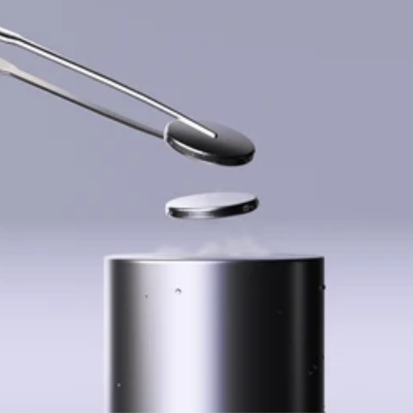
4. Magnetic Curiosities: Due to their incredible strength, neodymium magnets are often used in creative experiments and tricks, such as magnetic levitation demonstrations or DIY Air skateboard.
Conclusion
Neodymium magnets are a blend of science and innovation, but myths surrounding them can often obscure their true potential. By understanding their properties and debunking common misconceptions, we can appreciate their vital role in modern technology. Whether it’s in industrial machinery, green technology, or everyday gadgets, neodymium magnets continue to be indispensable and fascinating components of our world.
Axial fan air volume increase skills the key method to improve efficiency
In the field of industry and construction, axial fan as a common wind conveying equipment, widely used in the fields of ventilation, air conditioning and technology. However, sometimes we may need to increase the volume of the axial fan to meet specific needs. This article will explore some effective tips to help you increase the air volume and efficiency of your ac axial cooling fan.
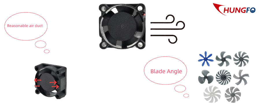
Reasonable design of air duct system:It is very important to optimize the design of air duct system to increase the fan air volume of axial cooling system fans . Our Chungfo axial cooling fan 110v ensures that the cross-sectional area and size of the air duct matches the outlet size of the axial flow fan, avoiding narrow bottlenecks or unnecessary resistance. In addition, we also install accessories such as elbows and diffusers according to different needs, which helps to reduce energy loss and air volume attenuation.
Adjust blade Angle:The blade Angle has an important influence on the output of axial fan. Our air cooler axial fans also change the output characteristics of the fan by adjusting the blade Angle. Generally speaking, increasing the blade Angle can increase the air volume of the axial fan. However, it should be noted that too large a blade Angle may lead to energy loss and increased noise, so it needs to be adjusted within an acceptable range.
Chungfo Electronic Technology company is not only engaged in the axial cooling fan Wholesale, but also engaged in silent axial fan Wholesale. If you have any questions about the cooling fan, you can consult us at any time.
Brushless cooling fan eliminates electromagnetic interference for you
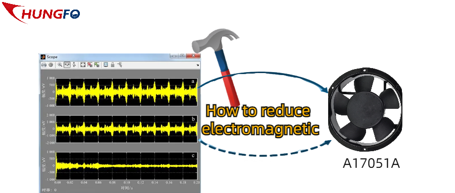
In the modern era of science and technology, the popularization and use of electronic equipment inevitably brings about the problem of electromagnetic interference. Especially in the use of cooling fans, traditional brushed fans often produce electromagnetic interference, which brings inconvenience to users. This time brushless cooling fan is your best choice. How does it reduce electromagnetic interference? Mainly through four ways:
Use an electronic controller instead of a mechanical commutator: Just like our A17051A industrial high-speed axial flow brushless cooling power cabinet fan uses an electronic controller instead of the mechanical commutator of the traditional brushed cooling fan. In this way, electromagnetic interference caused by mechanical friction can be reduced, while the electronic controller can precisely control the speed and current of the motor, thereby reducing electromagnetic radiation.
Ground and grounding: Some wholesale 24v DC brushless fans will also improve the ground and ground, good grounding can reduce electromagnetic radiation and interference. Ensure that the ground cables of the brushless cooling fan are securely connected to the grounding system of the entire system.
Centrifugal fan + Air Purifier = The success equation for fresh breathing!
Want a breath of fresh air? Choose a centrifugal fan with an air purifier! It's a winning combination, and let's see why.
First of all, the centrifugal fan can produce a high static pressure capacity during the rotation process, our centrifugal fan usually includes a rotating impeller and a spiral guide housing. This design can collect air in the center and spray it at a higher speed under the action of centrifugal force, resulting in a larger static pressure. This means that it can effectively capture and remove harmful substances such as particles, formaldehyde, and odors in the air to ensure the purity of indoor air.
Secondly, the application of centrifugal fans in air purifiers is also reflected in its silent performance. Some special designs of the blades of centrifugal fans will reduce the production of noise, just like our centrifugal fans usually use smooth blade curves to reduce the production of noise when the air flows. In some specific cases, we will also reduce the noise level of the centrifugal fan by increasing the number of blades, more blades can make the noise more easily isolated and dissipated. Noise is reduced, thus improving the user experience of the air purifier.
Our 12v centrifugal fan is a combination of the above two points, in addition to this fan, there are other fans you can choose, such as plastic centrifugal fans, brushless centrifugal fans, we are also a good choice for wholesale air centrifugal fans.
Cooling fan blade material A key choice for improved performance
Then the last part continues to discuss the important influence of blade material on the performance of the cooling fan.
(1) Blade material
Plastic blade:They are lightweight, low in manufacturing cost and can be quickly produced by injection molding. However, plastic blades generally produce more noise than other materials and may have lower strength and durability.
Fibrous composite material:It has good strength and durability, can provide lower noise and higher airflow efficiency, can improve the efficiency and output power of the fan.
Aluminium alloy:It is a commonly used blade material, with high strength, light weight and easy processing characteristics. Aluminum alloy has good thermal conductivity, can effectively dissipate heat, and improve the heat dissipation effect of the fan. The blades of our AC-F60300 air radiator cross flow fan are made of high-quality aluminum alloy metal material, which is not easy to deform, well-made, strong and durable frame, and long service life. In addition, the working temperature of the air radiator cross-flow fan is -10℃ ~ 70℃ ultra-high temperature range, aluminum structure, waterproof function is strong, suitable for most outdoor environments, this waterproof moisture-proof AC cross-flow cooling fan is especially suitable for outdoor advertising display heat dissipation.
Chungfo is a very experienced cooling fan manufacturer, have any questions about the cooling fan, you can come to us, we are very happy to serve you!
